Every flat sheet metal part that gets formed into a 3D shape depends on one critical calculation: bend allowance. Get it right, and the part fits perfectly. Get it wrong, and flanges come up short, holes end up in the wrong place, and entire production runs get scrapped. For fabricators working with CNC press brakes, understanding bend allowance is not optional. It is the bridge between what the designer draws and what the machine actually produces.
What Is Bend Allowance?
1. Definition and Importance
Bend allowance (BA) is the arc length of the neutral axis through the bend zone. It represents the amount of material consumed by the bend itself. When a flat sheet is bent, the material on the outside of the bend stretches while the inside compresses. Neither surface retains its original length. Bend allowance accounts for this material behavior, allowing you to calculate the true flat length required to produce a part with the correct finished dimensions.
Without bend allowance, a flat pattern is just a guess. The formed part will not match the drawing, and assembly becomes impossible.
2. The Neutral Axis and Why It Shifts
When sheet metal is bent, the material does not simply fold along a perfect line. The outer fibers elongate under tensile stress, while the inner fibers shorten under compressive stress. Between these two zones lies the neutral axis, a theoretical plane where the material is neither stretched nor compressed.
In an ideal bend, the neutral axis would sit exactly at the midpoint of the material thickness. In reality, it shifts toward the inside of the bend because the compressive zone is constrained by the surrounding material. The exact position of the neutral axis depends on the material type, bend radius, and bending method. This shift is what makes bend allowance calculation necessary.
3. How Bend Allowance Relates to Flat Pattern Length?
The flat pattern length of a sheet metal part equals the sum of all straight flange lengths plus the bend allowance for each bend. If your part has three bends, you need three bend allowance values. If any one is calculated incorrectly, the cumulative error multiplies across the part.
What Is Bend Allowance Formula?
1. The Standard Formula
The most widely used bend allowance formula is: BA = A × (π/180) × (R + K × T)
- BA = Bend Allowance
- A = Bend Angle (in degrees)
- R = Inside Bend Radius
- K = K-Factor
- T = Material Thickness
The K-Factor is the ratio of the neutral axis position to the material thickness. It typically ranges between 0.3 and 0.5, depending on the material and bending method. For a bend radius equal to material thickness, the default K-Factor is approximately 0.27324
Example:
For a 90° bend in 2mm mild steel with an inside radius of 2mm and a K-Factor of 0.4:
BA = 90 × (π/180) × (2 + 0.4 × 2) = 90 × 0.01745 × 2.8 = 4.398mm
This is the length of material consumed by the bend. If the two flanges are 30mm each, the flat length is 30 + 30 + 4.398 = 64.398mm. Program 64mm into the press brake, and the finished part will be undersized.
2. Why the K-Factor Is Not a Fixed Value?
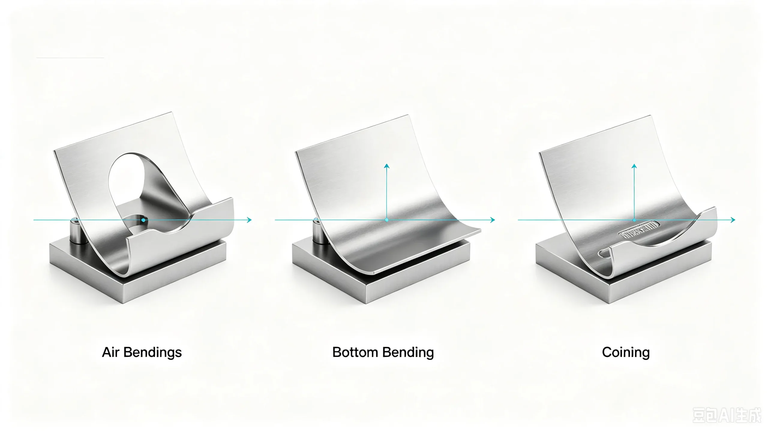
Many CAD programs use a default K-Factor of 0.5. That default is almost never correct for real production. The K-Factor changes with material type, tensile strength, inside bend radius, material thickness, and the bending method used. Air bending, bottom bending, and coining each produce different neutral axis positions, which means the same material bent the same thickness will require different K-Factors depending on the process.
So, using a fixed K-Factor for every job is one of the most common causes of flat pattern errors in sheet metal fabrication.
What Factors Affect Bend Allowance?
1. Material Type and Thickness
Different materials exhibit different springback and elongation behavior. Stainless steel and high-strength alloys require different K-Factors than mild steel or aluminum. Material thickness directly affects the neutral axis position. Thicker sheets have a larger compressive zone, pushing the neutral axis further inward.
2. Inside Bend Radius and Bend Angle
A larger inside radius increases the arc length of the bend, which increases bend allowance. The bend angle determines how much of that arc is actually formed. A 90° bend uses roughly half the arc length of a 180° bend for the same radius.

3. Bending Method and Tooling
Air bending, bottom bending, and coining create different stress distributions through the material thickness. Air bending produces the least material contact and the most springback, while coining forces full plastic deformation and nearly eliminates springback. Each method requires its own K-Factor calibration. The V-die opening width also influences the achievable inside radius, which in turn affects bend allowance.
How to Improve Bend Allowance Accuracy in Press Brake Bending?
1. Use the Correct Material Thickness
Material thickness is one of the most sensitive variables in the bend allowance formula. A 0.1mm error in thickness input can shift the calculated flat length by 0.2mm or more. Always measure the actual sheet thickness rather than trusting the nominal value from the material certificate.
2. Determine the Inside Radius from Actual Tooling
The inside bend radius is not always equal to the punch tip radius. In air bending, the inside radius is typically larger than the punch nose. Calculate or measure the actual radius produced by your tooling setup, and use that value in the formula.
3. Validate with Trial Bends
The most reliable way to improve bend allowance accuracy is to perform trial bends using the actual material and tooling. Measure the resulting flange lengths and bend angles, then back-calculate the K-Factor that matches your real production conditions. Store that value in your CNC program for future jobs.
4. Maintain Stable Material and Process Conditions
Batch-to-batch material variation can change the K-Factor even when everything else stays the same. Monitor incoming material properties, maintain consistent hydraulic oil temperature on hydraulic press brakes, and keep tooling in good condition. On electric servo press brakes, the ram positioning is not affected by oil temperature, which provides a more stable platform for repeatable bend allowance results.

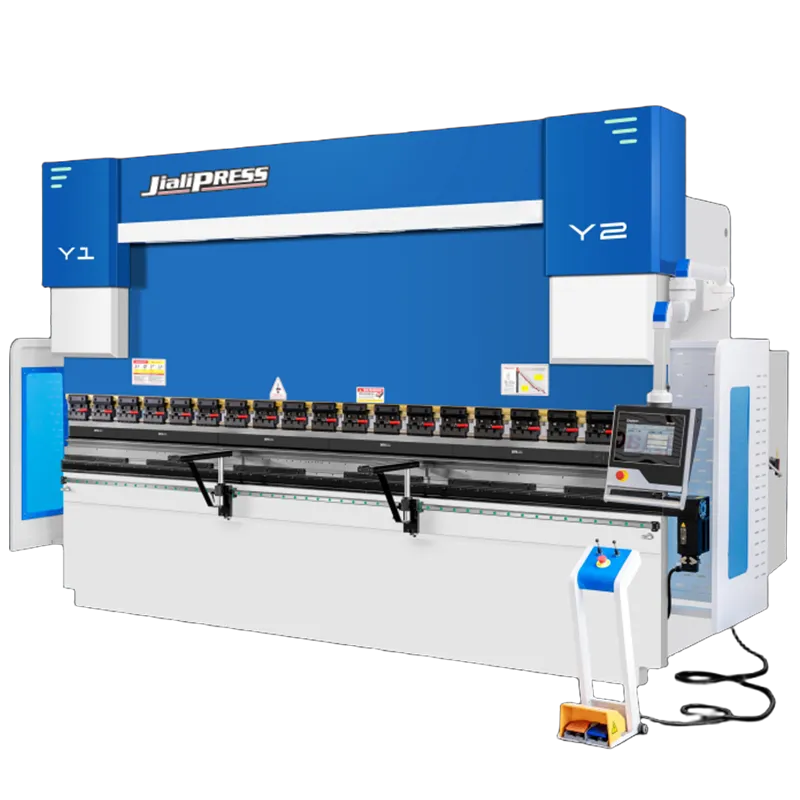
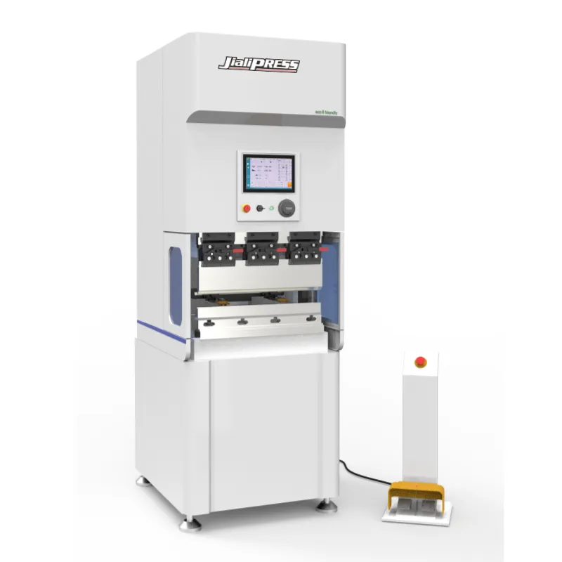
At JialiPress, it’s electric servo press brakes are engineered for the precision that bend allowance calculations demand. The Jiali achieves a backgauge positioning accuracy of 0.01mm using Taiwan HIWIN precision linear screw guideways, and the ultra-fast ram response of 2.1 seconds ensures consistent stroke depth on every cycle. The machines are equipped with advanced CNC control systems that allow operators to store material-specific K-Factors and springback compensation values for each job, reducing trial-and-error and improving first-part accuracy.

What Problems Are Caused by Incorrect Bend Allowance Calculation?
1. Flat Pattern Errors and Oversized Parts
If bend allowance is underestimated, the flat pattern will be too short, and the finished flanges will not reach the required length. If overestimated, the flanges will be too long. In either case, the part does not fit.
2. Increased Setup and Trial Bending
Incorrect bend allowance values force operators to spend extra time on trial bends, adjusting parameters, and re-measuring. This reduces productivity and increases labor cost per part.
3. Material Waste and Cost Increases
Every failed trial bend consumes material. In high-volume production, even a small flat pattern error repeated across thousands of parts can result in significant material waste and rework cost.
Tips for Applying Bend Allowance Correctly in Press Brake Production
- Identify target finished dimensions from engineering drawings.
- Calculate bend allowance and blank size based on material, thickness and bend parameters.
- Generate the correct flat blank pattern for laser or plasma cutting.
- Program corresponding bending parameters into your CNC press brake.
- Complete first-piece trial bending and measure all critical dimensions.
- Revise bend allowance values or machine parameters according to measured results.
- Launch mass production and continuously monitor dimensional consistency.
Conclusion
Bend allowance connects the flat sheet to the finished formed part. It depends on the neutral axis position, which shifts with material type, thickness, inside radius, and bending method. The K-Factor that drives the formula is not a fixed constant and must be calibrated for specific tooling and production conditions. Accurate bend allowance calculation reduces scrap, shortens setup time, and ensures that every part matches the drawing.
At JialiPress, it’s electric servo press brakes designed to make that data reliable. With high-precision ram control, stable backgauge positioning, and CNC systems that support material-specific compensation values, and can achieve consistent accuracy from the first bend to the last.